Osteokinematic movements pertain to the basic voluntary physiologic movements of the skeletal system. These are the macro joint movements that we see in everyday movements – flexion, extension, abduction, adduction, etc. For modeling purposes, the osteokinematic skeletal system can be viewed as a system of rigid links connected by joints.
In reality, human bones are not actually rigid structures as they do undergo deformations and encounter arthrokinematic movements as joint range of motion limits are reached. Arthrokinematic movements take place within the joint at the joint surfaces that we cannot see. These movements are not under voluntary control and are the result of a combination of three different types of arthokinematic motion: roll, glide (slide), and spin. The joint surface shape (concave or convex) and joint congruency will determine the type and amount of arthrokinematic motion. However, for the purpose of studying human motion, or kinematics, the human body is typically treated as an assemblage of osteokinematic rigid links and arthrokinematics are neglected.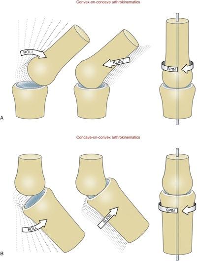 A rigid body is considered to be a structure that maintains a constant form despite the application of forces which cause the body to move. All of the particles making up a rigid body have fixed locations relative to each other – and thus the body cannot fracture, expand, distort, or otherwise change any of its macroscopic descriptors (moment of inertia, center of mass location, etc.) throughout the time interval encompassed by the analysis.
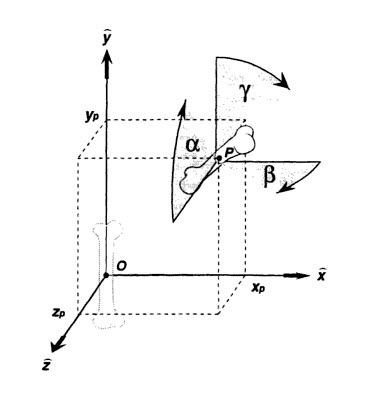
From Dynamic Modeling of Musculoskeletal Motion, “systems of moving bodies can be characterized by the number of generalized coordinates n necessary and sufficient to uniquely define the configuration of the system at any particular instant in time. This integer value n is referred to as the number of degrees of freedom possessed by the system, and does not included parameters fixed by geometry…The minimum number of parameter values required to determine the instantaneous configuration is the number of degrees of freedom…a rigid body moving unconstrained in Cartesian space has six degrees of freedom. The specification of a point location in 3D space requires three variables xp, yp, and zp. The location of one point on the rigid body thus requires three degrees of freedom. Three more degrees of freedom are required to define the orientation of the object (three rotation angles)…The instantaneous configuration can also be specified using two points and an angle, or three points, but these require seven and nine parameters, respectively.”
A vector is a mathematical representation communicating both magnitude and direction. Vectors can be used to represent physical quantities such as forces, moments, torques, positions, velocities, accelerations, angular velocities, and angular accelerations. A vector with a magnitude of one is known as a unit vector. A unit vector parallel to any vector is found by dividing the vector by its magnitude: When a unit vector is used to express the direction of a vector, a scalar multiplier may be used to conveniently express the magnitude.
Any vector in 3D space can be formulated by algebraically summing three noncoplanar vectors. Similarly, any vector may be decomposed into component vectors in any three noncoplanar directions. The most common decomposition utilizes a basis (i.e., a set of three noncoplanar vectors) comprised of mutually perpendicular unit vectors. Mathematically, any three noncoplanar vectors can be used to define a basis in 3D space. In rigid body analysis, a set of basis vectors will refer to the most commonly used basis, which is a set of mutually perpendicular unit vectors arranged in right hand fashion.
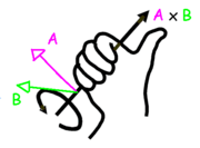
The right hand rule for vector cross products is the following: when the fingers of the right hand are initially aligned with the vector, A, and curled towards, B, through an acute angle, then, C, in a right handed system points in the same direction as the outstretched right thumb.
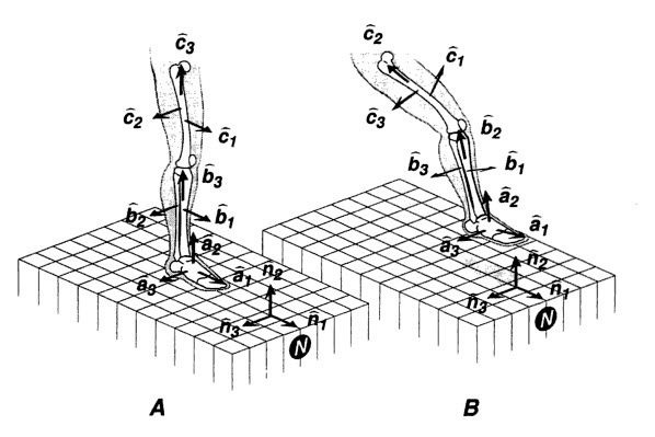
In rigid body analysis, a reference frame can be affixed to each rigid body, which moves and rotates along with the body’s movements as if rigidly attached to the rigid body (bone) of interest. Because both the reference frame and the body are rigid, and affixed to one another, the motions of the reference frame and the body are equivalent. For example, in the picture below, the tibia is shown hanging from the knee in 2 positions with respect to a fixed femur. With the tibia considered to behave approximately as a rigid body, reference frames and basis vectors can be affixed to the shank in such a way that the “1” unit basis vector of each reference frame points anteriorly, the “2” basis vector points superiorly, and the “3” basis vector points laterally when standing erectly.
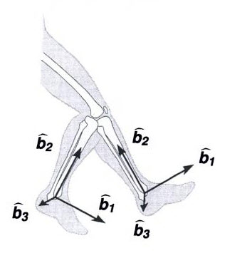
This same approach can be applied to the entire lower leg including the thigh and foot. During erect stance (A), the basis vectors are defined in alignment with the N basis vectors. When the segments are moved (B), the basis vectors move because the vectors are rigidly affixed to the segments.
It is important to note the distinction between a set of right-handed mutually perpendicular basis vectors and a reference frame. Reference frames have well defined origins, whereas bases only define the directions of the individual basis vectors. Reference frames are therefore bases with origins defined in Cartesian space.