I was first exposed to inertial motion tracking technology 13 years ago while at Callaway Golf. At the time we were already using an active optoelectronic motion capture system (NDI Optotrak) and an electromagnetic motion tracking system (Polhemus) for swing analysis studies. We also had an on-board diagnostic (OBD) shaft-based data acquisition system that was used as well in research studies. One of my many projects was to develop player swing profiles for different swing types using these technologies.
One of the first things I did was to ask our measurement systems group to change the OBD technology from strain gaged clubs at the butt and tip end of the shaft to inertial motion sensors. The reason for this was five-fold:
- Allowed for direct measurement of player swing inputs using angular rate gyros and linear accelerometers at the butt end of the club.
- Allowed direct comparison to optical motion capture outputs in synchronized swing studies.
- Preliminary motion capture results had indicated that wrist release and shaft closure angular rates could be used for player profiling; this design allowed for direct comparison and could be used on a lot more golfers than possible in the motion capture lab.
- By housing the design in a modular shuttle design that could be removed from the butt end of the shaft, the OBD II system could be used in any club desired for testing. Previous strain-gaged clubs were dedicated test clubs and we could only test on a few clubs at once.
- The player would have no idea that it was an instrumented club and they could take the club anywhere – in the lab, in our fitting center, out on the test range, or out on the course.
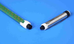

The end result was an absolute success. Our measurement systems group did an unbelievable job building a modular shuttle OBD II design that could be used in any club. The technical specs that I provided were very demanding and exceeded the range of all commercially available sensors at the time. Through correspondence with the device manufacturers, we were able to expand the range through the addition of a resistor, dropping the supply voltage, and biasing the angular rates in one direction. We were able to calibrate the system through a customized testing apparatus and obtained a maximum calibrated range of 3,500 degrees/second.