Inertial Measurement Units (IMU) are the latest advancement in motion tracking having been adapted from aerospace and military industries. An IMU is a Micro-Electro-Mechanical System (MEMS) electronics module and is typically comprised of 3 accelerometers, 3 gyroscopes, and optionally 3 magnetometers. IMUs with 3 axis accelerometers and 3 axis gyroscopes (either as tri-axial sensors or 3 independent axial sensors) are commonly referred to as 6 degrees of freedom (DOF) IMU sensors. The inclusion of a 3 axis magnetometer is some times referred to as 9 DOF IMU sensors; however, technically these should still be referred to as 6 DOF IMU sensors with associated 3 DOF digital compass (magnetomers) as technically the magnetometer sensors are not inertial sensors.  In most modern applications, the accelerometers, gyroscopes, and magnetometers used in 6 DOF and 9 DOF IMUs are usually each triad sensors, which insures axis orthogonality. Axis orthogonality is very important for orientation matrix calculations. In an accelerometer triad, the sensor generates three analog signals describing the accelerations along each of its axes produced by and acting on the object to which it is attached. The most significant of these sensed accelerations is the acceleration caused by gravity. There are two types of gyroscopes: an integrating rate gyro measures changes in orientation whereas a rate gyro measures changes in angular velocity. A tri-axial rate gyro sensor outputs three analog signals describing the object’s angular velocity changes about each of the three sensor axes. Even though the IMU is not located at the object’s center of mass, the angular rate measurements are not effected by linear or angular accelerations. Most modern day IMUs also include a magnetometer triad which serves basically as a digital compass in the Earth’s significant magnetic field and is used to determine absolute orientation of the IMU in the Earth’s North-East-South-West (NESW) global reference frame. Magnetometers are used to help define an initial orientation and further positions are derived by integrating the gyroscope data.
Independently these sensors excel at different things, but the combination of these 3 sensor types in a 9 DOF IMU offers a very powerful motion tracking technology. Magnetometers offer very poor orientation accuracy for fast movements, but exhibit almost zero drift over time. An integrating scheme using angular rate gyros reacts quickly and produces accurate rotations to quick movements, but errors are accumulated over time resulting in drift. The integration routine requires starting from a known orientation. Combining the inputs from all 3 sensors allows for quick and accurate position and orientation determination with a small amount of drift over time if an advanced Kalman filtering routine is implemented.
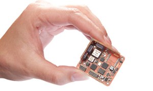
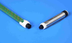
In most real-time 9 DOF IMU applications, an on-board microprocessor is also included to collect data from the 3 sensors through an analog-to-digital converter (ADC). A main processor is also used through some type of communications interface. The final form factor of the circuit design will be dependent upon the environment the 9 DOF IMU will be used. Size, weight, and shape all become important form factor design variables when 9 DOF IMU systems are used with humans in motion tracking applications. The 2 images below are form factor designs for the XSENS inertial sensors. 

One important factor for IMU motion tracking is the technical specifications required for the board design. This is especially true for high speed movement patterns associated with elite athletic performances. While tri-axial accelerometers and rate gyros have become more mainstream, they often times are not adequate for specific high speed motion activities. In some cases, it may be necessary to use 3 separate single axis sensors and use circuit board design to insure orthogonality of the 3 axes. While the singular axis sensors may offer flexibility in specs for the IMU design, it is imperative that orthogonality of the axes is obtained in the circuit board design. Beyond possibly having to use single axis rate gyros, the range of the single axis sensors may also need to be expanded beyond the tech specs of the sensor. This is especially true for rate gyros used in overhead throwing activities. MEMS device manufacturers often provide instructions for extending the range of rate gyros by incorporating resistors, dropping the supply voltage, and/or biasing the rate gyro in one direction. Through these steps it is possible to custom design IMU sensors to meet demanding requirements. It is imperative that orthogonality of the 3 axes is maintained and a calibration procedure needs to be implemented to verify the linearity throughout the extended range. A thorough review of internal shoulder angular rate measurements in baseball pitching provides a more detailed look at these design change possibilities.
While at Callaway Golf, I worked with our Measurement Systems group on the design, development, and testing of a modular on board diagnostic (OBD) tetherless shuttle design powered by rechargeable batteries that could slide in and out of any shaft at the butt end to directly measure the player’s swing motions. We had both 6 DOF and 9 DOF IMU designs that we used in our Player Performance Center. If we did not tell a player that the shuttle was inside the shaft underneath the grip, they had no idea that it was even there. Our measurement systems group did a great job on the design meeting very demanding tech specs yet housing it in a form factor that could slide in and out of the butt end of any shaft that we desired to test with. 
Inertial Motion Tracking Advantages
- Inertial motion tracking systems offer real-time motion tracking visualization and requires no post-processing.
- Inertial sensors can be used anywhere – inside or outside and with no restrictions on capture volume.
- Inertial sensors do not suffer from any line-of-sight occlusions or data dropouts.
- IMU sensors have much higher sampling rates, typically at least 1000 Hz dependent upon the design.
- Multiple subjects can be captured simultaneously with multiple IMU setups.
- Inertial sensors directly measure linear accelerations and angular rate changes without the need for differentiating positional data. This allows direct estimation of force data.
- Inertial sensors offer great versatility in design possibilities and it is fairly straightforward to get custom designed sensors for specific needs.
- Inertial tracking systems are less expensive than both optical (much less) and magnetic tracking systems. The size and cost of the MEMS components will continue to drop.
Inertial Motion Tracking Disadvantages
- Inertial motion tracking systems with multiple IMU sensors can be restrictive and impede the capture subjects’ movements for certain activities.
- IMU sensors suffer from positional drift over time.
- Global position data is not provided and must be calculated using appropriate associated sensor outputs (magnetometers and/or GPS) with advanced Kalman filtering routines.
- Positional data is not as accurate as both optical and magnetic tracking systems as it has to be estimated, as opposed to directly measured in those systems.
